Bilge Pump sensor replacment
Replacing the bilge pump sensor on a 2004, hull 1006
Total time: (1.5 to 2 hours depending on your comfort level with marine electrical systems)
My dock neighbors were reporting that my bilge pump was not shutting off after engaging. After several calls it became aparent that my sensor was getting stuck, even after an attempt to clean it up.
Here is a quick overview on this very *easy* repair, and you do NOT need to drill any more holes in your bilge!!!!!
Tools and material required:
- Long and thin(er) phillips head screw driver.
- Wire cutter
- Wire crimping tool
- 2 Waterproof solderless butt connectors, 14 awg
- Heat source (I used an aim and flame)
- JOHNSON ULTIMA BILGE SWITCH Defender P/N 502961
- 1 Waterproof fuse, 14 awg (I got mine from West Marine, rubber yellow, with crimp connections.)
- Fuse, 10 amp
- Volt Ohm meter
- Empty and dry the bilge as best as possible.
- Turn off the bilge pump from the panel.
- Remove the sensor from the base using the screw driver. *Keep* the two PH screws.
- Cut the wire tie used to secure the wire bundle to the stringer.
- Remove the lower/smaller wire protector. It is actually partially "inside" the larger diameter wire protector that goes to the bilge pump.
- Follow the three wires to the existing solderless butt connectors. See pictures HERE and HERE.
- Cut all three wires (2 brown, one black) about 2 inches from the existing plastic yellow butt solderless butt connectors.
- ** Note ** - I did NOT cut the wires "above" the existing solderless butt connectors as this would have forced me to remove the port floor board and work in the "pan". Also, the wire from the panel is thicker. The existing stock sensor wires were 14 awg, so no need to use "reducers",
- Discard the existing sensor. You will quickly realize why it failed.
- Remove the Johnson sensor from its package. Note that the mounting pad for the Johnson is nearly identical to the stock installed by Catalina.
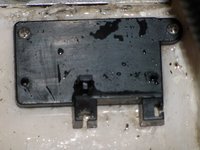
- View the stock mounting pad HERE and HERE.
- Remove the stock mounting pad by removing the two screws embedded in the fiberglass of the bilge. *Keep* the two PH screws.
- Place the new sensor mounting pad over the two holes, and fasten them using the two screws.
- Place the new sensor on the mounting pad and fasten with one screw.
- Work the two wires into the smaller wire protector and then into the larger wire protector, as a "rough fit" for length.
- Strip an appropriate amount of insulation from the two brown wires from the panel as well as the black ground wire.
- Make sure the two wires from the panel were NOT touching anything wet.
- Turn on the bilge pump at the panel with the option switch on "Auto".
- Using the Volt Ohm meter, determine which wire from the panel is now "hot". Just to be sure the wiring is correct, validate the other is NOT hot.
- Switch the bilge pump back off on the panel.
- For a dry run and test, roughly wire up the sensor per the instructions that came with the Johnson sensor.
- Connect the "hot" wire from the panel to the hot wire on the Johnson sensor. Connect the other wire. (You do NOT need the black ground anymore...)
- Turn on the panel, with the option switch on "Auto".
- Validate the pump does NOT turn on.
- Touch the two circles on the sensor (see instructions), and validate the pump turns on.
- Turn the option switch to "Manual". Validate the pump comes on.
- Turn the option switch back to "Auto" and validate the pump turns off.
- If everything worked as described above, it is wired correctly.
- Turn off the bilge pump at the panel.
- Roll up the black ground wire and secure it. I tied it to the bilge pump so it could be fished back down into the bilge for something else.
- Disconnect the "rough" connections.
- Estimate the required amount of wire from the new sensor. I kept an extra 2 inches and loosely wire tied them. Cut the wires to length.
- Using one of the waterproof solderless butt connectors, connect/crimp the *NON HOT* wire from the panel first. (Just the way I did it...)
- On the hot wire from the panel, attach the waterproof fuse to one end, and the hot wire from the bilge sensor to the other. (this took some effort to fit correctly)
- ** NOTE ** - To get the wires through the waterproof fuse you will need to cut the bare exposed wire, and then "re-strip" the insulation to make the connections.
- Insert a 10 amp fuse and repeat the above tests on the sensor again to be sure all connections are sound.
- Move any wires out of the bilge, and test with real water.
- Secure the sensor to the sensor pad with the second screw.
- Use the heat source to melt the ends on the waterproof solderless butt connectors.
- Re-wrap all the wires in the black plastic wire protector.
- Re-secure the wire bundle to the stringer as it was attached before.
- Go away happy that you didn't have to drill any additional holes in your boat.