Testing Speed Transducer
Tag: diagnostics electronics
Marine Transducers
How do I test an Airmar paddle-wheel speed sensor?
The speed function of our sensors is best tested using an oscilloscope, however a simple test may be performed using a digital or analog multimeter. This article was written by the Airmar technical folks and is altered slightly to include more details.
Our sensors are designed to work with various manufacturers products and may accept a supply voltage between 5 V - 12 V. Keeping this in mind, the output square wave voltage generated when the paddlewheel rotates is equal to the input supply voltage, i.e. if 5 VDC is supplied, a 5 VDC square wave is generated as an output, if 12 VDC is supplied, a 12 VDC square wave is generated.
To test a sensor that has a molded connector using a conventional digital multimeter, perform the following:
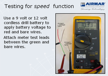
For convenience, it may be easier to perform this test by supplying 12 VDC directly to the sensor from the battery if a molded connector is in place. Using the wiring diagrams to identify the correct pins, insert wires or test pins into the appropriate contacts to supply 12 VDC to the sensor and to take measurements as described below.
For these tests, you set your volt meter to a DC Volts measurement. The voltage range will be in the 9-12v range in case your meter isn't auto-ranging.
To test a sensor that has open wire contacts using a conventional digital multimeter, perform the following:
- Connect the speed sensor to the speed display .
- Measure across red and shield(ground) on the sensor wiring. this is the dc supply voltage from the display unit which must be between 5 V and 12 V.
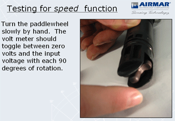
- Measure across green and shield (ground) on the sensor wiring and spin the paddlewheel. You should read a fluctuating voltage(square wave) between 0 VDC and your measured input supply voltage.
- Continue to measure across green and shield and slowly rotate the paddlewheel 1/4 revolution at a time. Each 1/4 turn should generate an on/off status as an output, i.e. 1/4 turn = 0 VDC, next 1/4 turn = supply voltage, next 1/4 turn = 0 VDC, etc.
Results:
--If you fail to obtain a supply voltage from the display unit (between the terminals where the Red and Bare wires connect) then there is a fault with the display.
--If you fail to obtain an output signal, the paddlewheel sensor is faulty.
Note: You can leave the Red and Bare wires connected to the display unit for power if you don't want to hook up a 9v or 12v battery to the sender. You will be watching for a Signal voltage with the volt meter on "DC Volts" setting between the Bare and Green wires.
.jpg)